2. Get Data from Blynk
You will learn how to control the circuit with Blynk in this chapter. Let’s light up the LEDs over the Internet!
Required Components
In this project, we need the following components.
It’s definitely convenient to buy a whole kit, here’s the link:
Name |
ITEMS IN THIS KIT |
LINK |
|---|---|---|
3 in 1 Starter Kit |
380+ |
You can also buy them separately from the links below.
COMPONENT INTRODUCTION |
PURCHASE LINK |
|---|---|
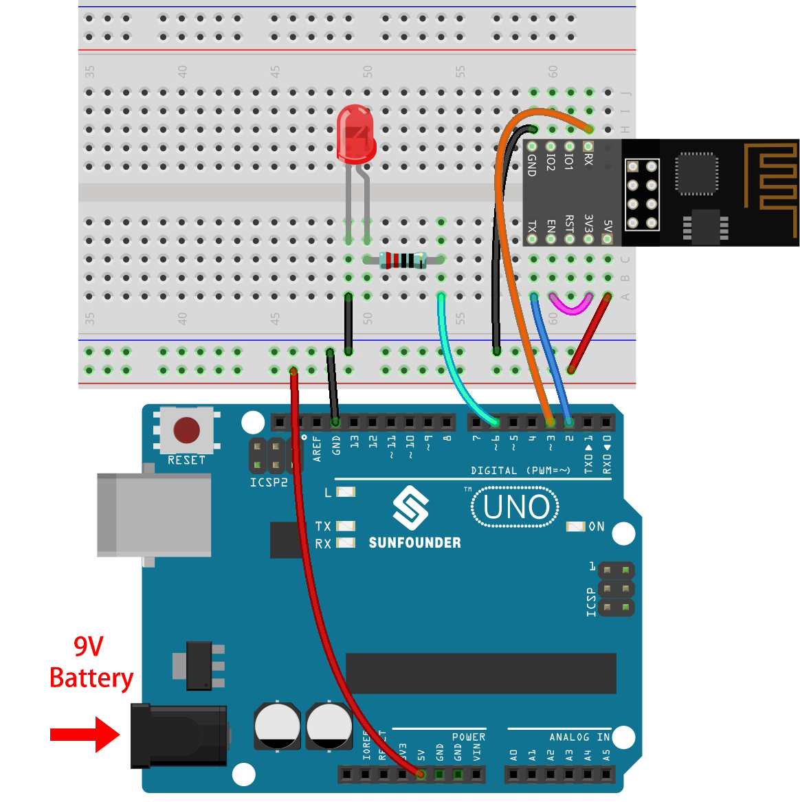
1. Build the Cirduit
Note
The ESP8266 module requires a high current to provide a stable operating environment, so make sure the 9V battery is plugged in.
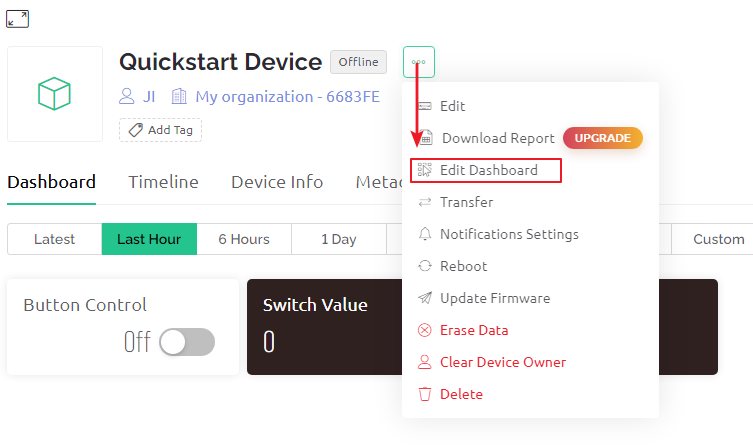
2. Edit Dashboard
Go to the Quickstart Device you created earlier, click on the menu icon in the upper right corner and select edit dashboard.
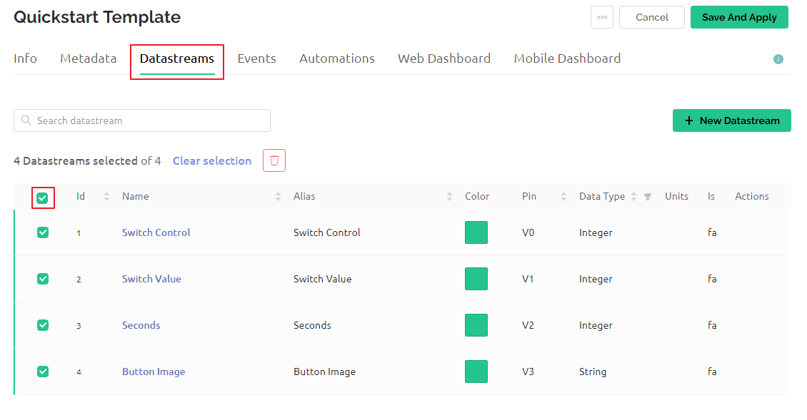
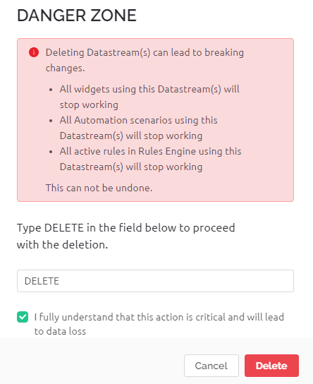
Datastreams allow the widgets on Blynk and the code on the R3 board to recognize each other. To experience the complete configuration process, remove all Datastreams from the Datastreams page.
Please read the warning carefully and confirm it is correct before deleting the Datastreams.
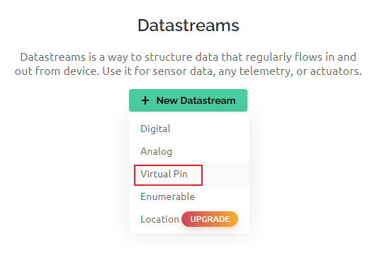
Create a Datastream of type Virtual Pin, which will be used to control the LED using Blynk’s switch.
Configure the Virtual Pin. As the button and LED only need to be ON and OFF, set DATA TYPE to
Integerand MIN and MAX to0and1.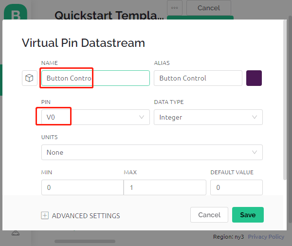
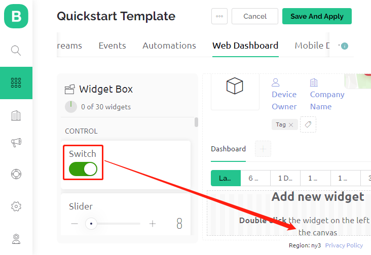
Go to the Web Dashboard page and delete the existing widgets.

Drag and drop a switch widget from the Widget Box on the left.
Now to set it up.
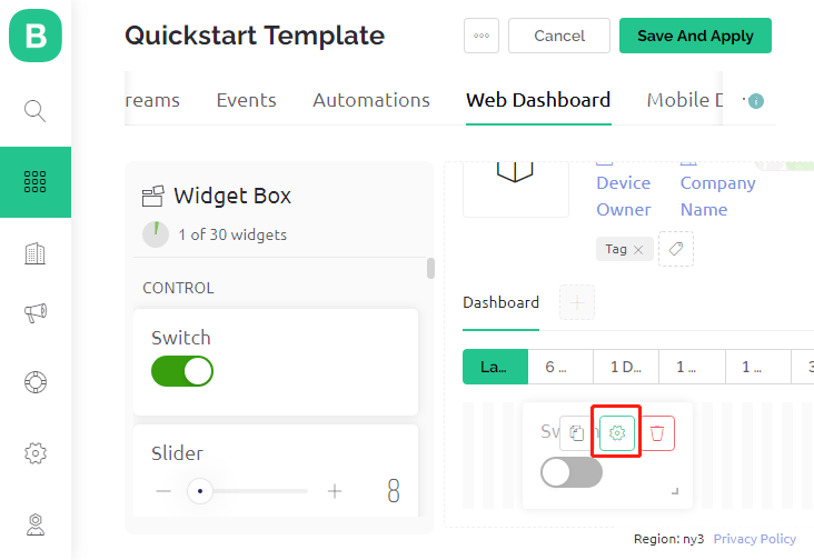
Select Datastream as the one you set earlier.
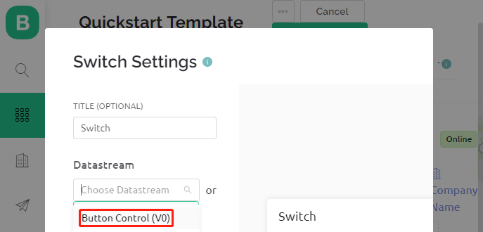
After selecting Datastream, you will see a few custom settings, then press Save.
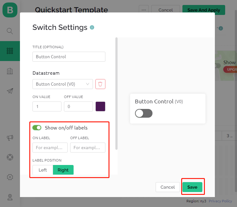
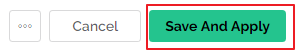
Finally, click Save And Apply.
3. Run the Code
Open the
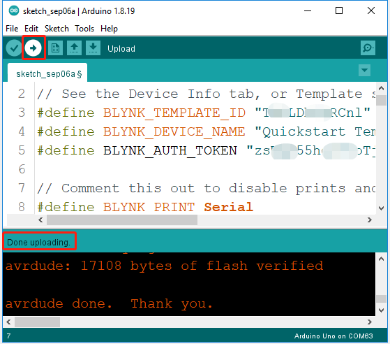
2.get_data_from_blynk.inofile under the path of3in1-kit\iot_project\2.get_data_from_blynk, or copy this code into Arduino IDE.Replace the
Template ID,Device Name, andAuth Tokenwith your own. You also need to enter thessidandpasswordof the WiFi you are using. For detailed tutorials, please refer to 1.4 Connecting the R3 board to Blynk.After selecting the correct board and port, click the Upoad button.
Open the Serial monitor(set baudrate to 115200) and wait for a prompt such as a successful connection to appear.
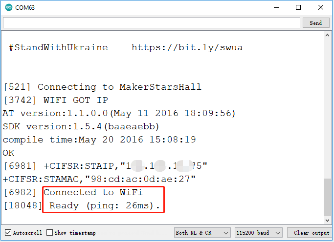
Note
If the message
ESP is not respondingappears when you connect, please follow these steps.Make sure the 9V battery is plugged in.
Reset the ESP8266 module by connecting the pin RST to GND for 1 second, then unplug it.
Press the reset button on the R3 board.
Sometimes, you may need to repeat the above operation 3-5 times, please be patient.
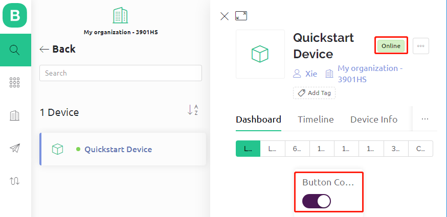
Back at Blynk, you can see that the status has changed to online and you can now use the switch widget on blynk to control the LED connected to the R3 board.
If you want to use Blynk on mobile devices, please refer to How to use Blynk on mobile device?.
How it works?
The difference between the code in this project and the code in the previous chapter 1.4 Connecting the R3 board to Blynk is the following lines.
const int ledPin=6;

BLYNK_WRITE(V0)
{
    int pinValue = param.asInt(); // assigning incoming value from pin V0 to a variable
    // You can also use:
    // String i = param.asStr();
    // double d = param.asDouble();
    digitalWrite(ledPin,pinValue);
}

void setup()
{
    pinMode(ledPin,OUTPUT);
}
Regarding the pinMode and digitalWrite of the ledPin, I’m sure you’re already familiar with them, so I won’t go over them again. What you need to focus on is the BLYNK_WRITE(V0) function.
What it will do is that when the value of Blynk’s V0 changes, Blynk.Cloud will tell your device “I am writing to Virtual Pin V0”, and your device will be able to perform something once it gets this information.
We created the V0 Datastream in the previous step and applied it to the Switch Widget.
This means that every time we operate the Switch Widget, BLYNK_WRITE(V0) will be triggered.
We write two instructions in this function.
int pinValue = param.asInt();
Get the value of V0 and assign it to the variable pinValue.
digitalWrite(ledPin,pinValue);
Write the value of V0 obtained to the ledPin, so that the Switch widget on Blynk can control the LED.